Deciphering Elctrical Signals | The challenge SIGINT from CTF.SG CTF 2022
The contests of this post were originally from this github repository.
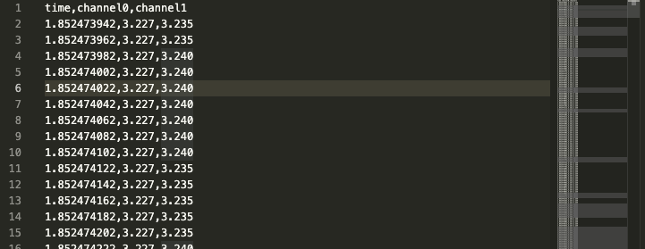
The contestant is given a large .csv file named analog.csv. It is presented to the contestant as data extracted from the wires of a crashed satellite.
It was the most convoluted and challenging CTF challenge I had ever solved. It remained unsolved throughout the CTF and it took me an additional day afterwards to solve. Either way, it was still a wild ride and I appreciate how it exposed me to a brand new type of cybersecurity that I had never heard of before.
- Look at the CSV
- There are 3 columns. One stores time information and the other 2 store floating point data. It is unclear what the 2 columns/channels represnt.
The column names are slightly different from what the file was originally given, since I had initially deleted them.
- There are 3 columns. One stores time information and the other 2 store floating point data. It is unclear what the 2 columns/channels represnt.
- Convert CSV data to .wav
- The data being in a linear format with respect to time reminded me of sound waves. So, I converted the CSV file into 2 wav files for each channel with the follwing python script:
    #!/usr/bin/python
    import wave
    import numpy
    import struct
    import sys
    import csv
    from scikits.samplerate import resample

    def write_wav(data, filename, framerate, amplitude):
        wavfile = wave.open(filename, "w")
        nchannels = 1
        sampwidth = 2
        framerate = framerate
        nframes = len(data)
        comptype = "NONE"
        compname = "not compressed"
        wavfile.setparams((nchannels,
                            sampwidth,
                            framerate,
                            nframes,
                            comptype,
                            compname))
        print("Please be patient whilst the file is written")
        frames = []
        for s in data:
            mul = int(s * amplitude)
            # print "s: %f mul: %d" % (s, mul)
            frames.append(struct.pack('h', mul))
        # frames = (struct.pack('h', int(s*self.amp)) for s in sine_list)
        frames = ''.join(frames)
        for x in xrange(0, 7200):
            wavfile.writeframes(frames)
        wavfile.close()
        print("%s written" %(filename))


    if __name__ == "__main__":
        if len(sys.argv) <= 1:
            print("You must supply a filename to generate")
            exit(-1)
        for fname in sys.argv[1:]:
            data = []
            for time, value, value2 in csv.reader(open(fname, 'U'), delimiter=','): #This where I lazily modified the code to copy data from either of the 2 columns from the CSV file.
                try:
                    data.append(float(value)) # Here, channel 0 data is being read from while channel 1 data is being discarded. Replace value with value2 to read channel 1 data instead.
                except ValueError:
                    pass # Just skip it
            print("Generating wave file from %d samples" % (len(data),))
            arr = numpy.array(data)
            # Normalize data
            arr /= numpy.max(numpy.abs(data))
            filename_head, extension = fname.rsplit(".", 1)
            # Resample normalized data to 44.1 kHz
            target_samplerate = 44100
            sampled = resample(arr, target_samplerate/100000.0, 'sinc_best')
            write_wav(sampled, filename_head + ".wav", 100000, 32700)
Adapted from https://gist.github.com/Pretz/1773870
- I also combined the two .wav files to a singular stereo .wav file with Audacity.
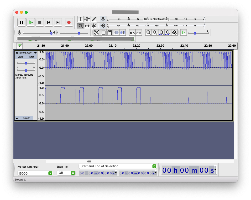
- The waveforms, combined with the challenge description mentioning wires in a crashed satellite, led me to suspect that this is an alternating current.
I also tried to interpret the generated audio as morse code and a SSTV signal, even comparing it to the audio on the Voyager Golden Records, but those methods were dead ends. I had to remind myself that the audio was merely a representation. In addition, I tried to extract steganographic LSB data from the .wav files, but I just got a lot of nothing.
- Extract data from waves
-
Initially, I followed this tutorial because I didn’t read the challenge description clearly and I had assumed that the data were measurements of radio waves. Using Inspectrum, the peaks of the waves were laid bare but I got seemingly useless data.
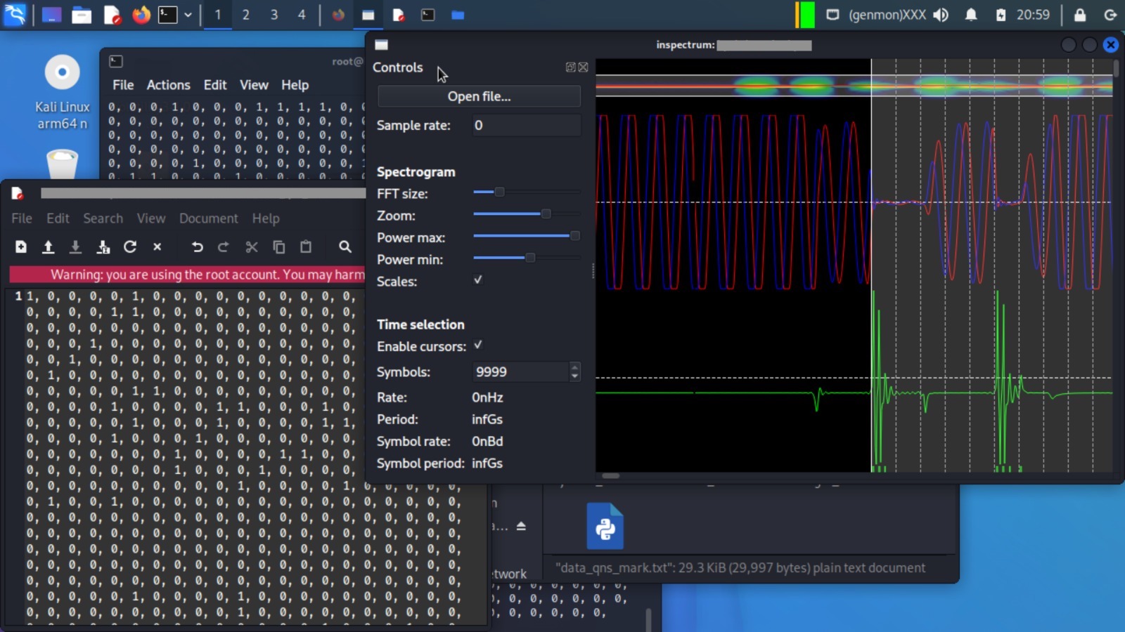 I had to use this script to convert the csv table data to a .iq file:, using this as a guide.
I then imported the data in its various forms into Digilent WaveForms. I noticed that the CSV file seemed to fit pefectly in that program, which confirmed my belief that the data were elctrical currents.
I had to use this script to convert the csv table data to a .iq file:, using this as a guide.
I then imported the data in its various forms into Digilent WaveForms. I noticed that the CSV file seemed to fit pefectly in that program, which confirmed my belief that the data were elctrical currents. 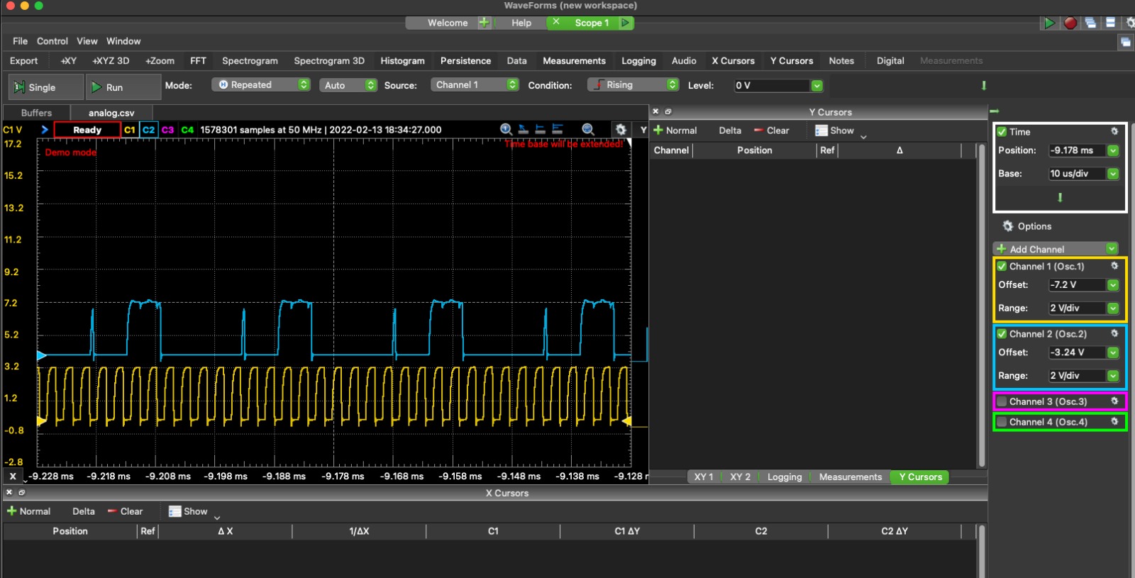 I started to realise that the data must be some kind of protocol, but no readable ASCII data seemed to come up when I tried to use WaveForm’s logical analyser. I was confused, because I thought the flag must have been transmitted through the eletrical current itself.
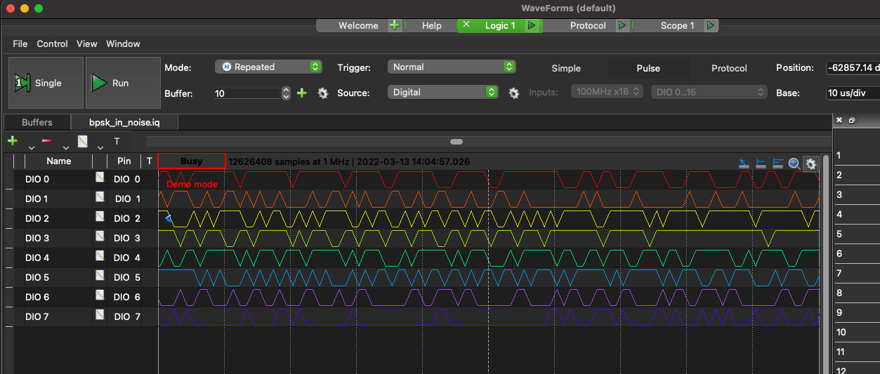
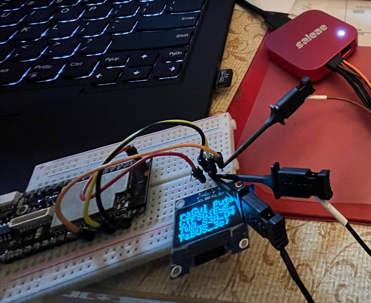
- I had to ask the challenge author, R4GUL, for hints and R4GUL revealed the protocol to be I2C, and recommended to me sigrok’s PulseView. R4GUL also told me that I had to further analyse the data after decoding it, and to look out for the signature used by the communicating device as its device address to identify the type of device and then read its datasheet for instructions on deciphering the decoded data.
- I imported the 2-channel .wav file into PulseView, converted both channels to logic via threshold, and opened up a I2C decoder with the 2 channels as its clock and data channels.
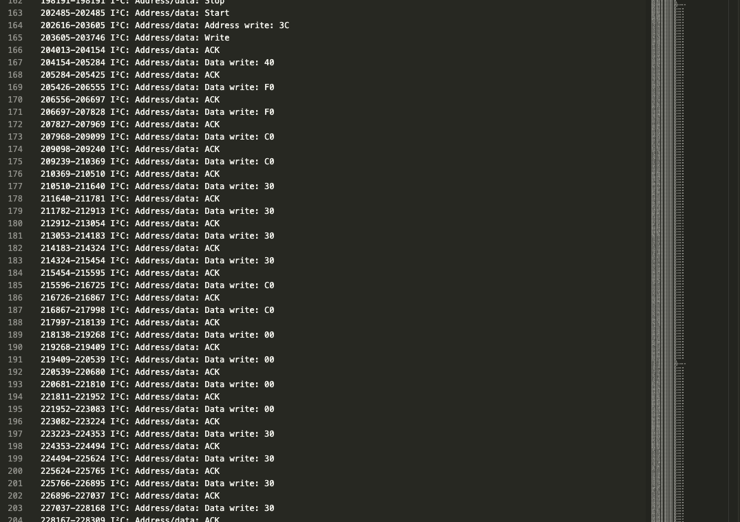
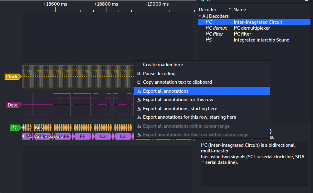 The address written is 0x3C, a monochrome OLED(specifically SSD1306). This was confirmed by R4GUL.
 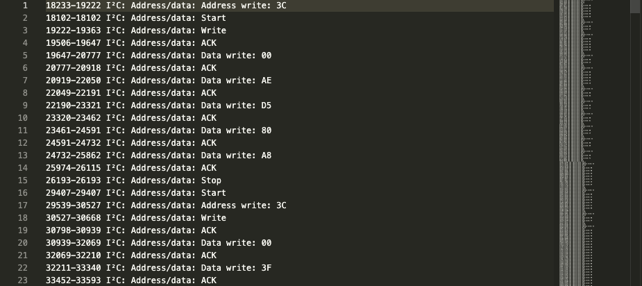 Now, we finally reach the last stage of this challenge: deciphering the commands being sent to the OLED monitor.
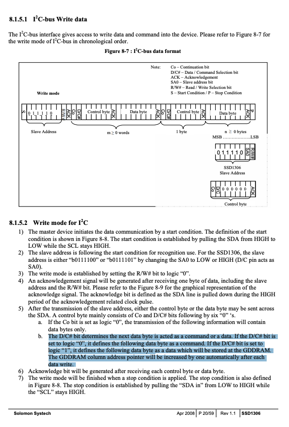
 - Data write 0x00 (0b00000000) indicates that the next byte contains a command, while data write 0x40 (0b01000000) indicates that the next byte is to be sent to the Graphics Display Data RAM(GDDRAM) (the bytes represents pixels to be displayed on the screen). This is because the 7th bit (from the LSB) indicates what is to be done with subsequent bytes.
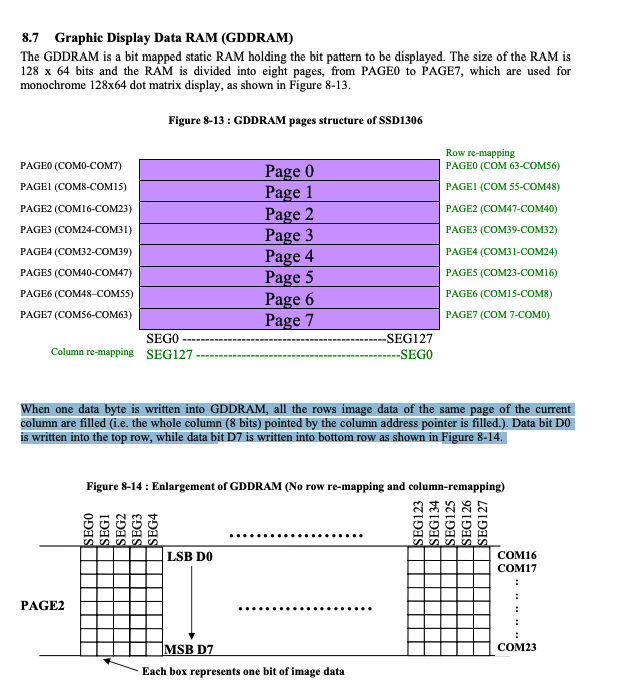
- A data byte that represents pixel data actually stores the on or off states for a column of 8 pixels, MSB towards the bottom and LSB towards the top.. A set of data bytes is essentially a N x 8 pixel image.
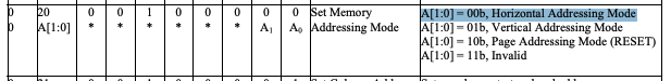
- However, the OLED only has finite width and this long strip of 8 pixel columns must wrap around eventually. The OLED has 3 addressing modes to deal with this. The one most relevant to us is horizontal addressing mode, which is basically from left to right, advance to start of next line when you reach the end of current line.
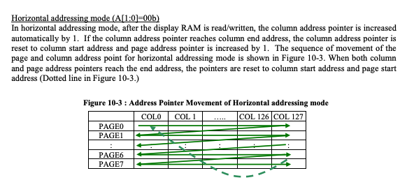
- In the I2C dialogue we see the command 0x20 (0b00100000).
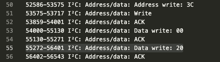
- 0x20 sets the addressing mode to horizontal addressing mode.
- Eventually, scrolling through the I2C communication dialogue, we see a section of bytes that seem to be nothing but writes to the GDDRAM.
- After a lot of text deleting we get a clean set of graphics bytes.
F0 F0 C0 C0 30 30 30 30 C0 C0 00 00 00 00 30 30 30 30 C0 C0 00 00 00 00 FC FC 03 03 03 03 03 03 0F 0F 00 00 F0 F0 00 00 00 00 00 00 F0 F0 00 00 00 00 03 03 FF FF 00 00 00 00 00 00 00 00 00 00 00 00 00 00 00 00 00 00 FF FF C3 C3 C3 C3 C3 C3 3C 3C 00 00 F0 F0 00 00 00 00 00 00 F0 F0 00 00 30 30 30 30 FF FF 30 30 30 30 00 00 C0 C0 30 30 30 30 30 30 30 30 00 00 00 00 00 00 00 00 00 00 3F 3F 00 00 00 00 00 00 00 00 00 00 0C 0C 33 33 33 33 3F 3F 30 30 00 00 0F 0F 30 30 30 30 33 33 3F 3F 00 00 0F 0F 30 30 30 30 0C 0C 3F 3F 00 00 00 00 30 30 3F 3F 30 30 00 00 00 00 00 00 00 00 00 00 00 00 00 00 00 00 3F 3F 00 00 00 00 00 00 00 00 00 00 0F 0F 30 30 30 30 0C 0C 3F 3F 00 00 00 00 00 00 0F 0F 30 30 0C 0C 00 00 30 30 33 33 33 33 33 33 0C 0C 00 00 00 00 00 00 00 00 00 00 FC FC 03 03 03 03 03 03 0C 0C 00 00 0F 0F 03 03 FF FF 03 03 0F 0F 00 00 FF FF C3 C3 C3 C3 C3 C3 03 03 00 00 3C 3C C3 C3 C3 C3 C3 C3 0C 0C 00 00 FC FC 03 03 03 03 03 03 0F 0F 00 00 00 00 C0 C0 3C 3C 03 03 00 00 00 00 FF FF C3 C3 C3 C3 C3 C3 03 03 00 00 F0 F0 00 00 00 00 00 00 F0 F0 00 00 FF FF C3 C3 C3 C3 C3 C3 03 03 00 00 00 00 00 00 00 00 00 00 00 00 00 00 00 00 00 00 00 00 00 00 0F 0F 30 30 30 30 30 30 0C 0C 00 00 00 00 00 00 3F 3F 00 00 00 00 00 00 3F 3F 00 00 00 00 00 00 00 00 00 00 0C 0C 30 30 30 30 30 30 0F 0F 00 00 0F 0F 30 30 30 30 33 33 3F 3F 00 00 00 00 00 00 0F 0F 30 30 00 00 00 00 3F 3F 30 30 30 30 30 30 30 30 00 00 30 30 C3 C3 C3 C3 C3 C3 3F 3F 00 00 3F 3F 30 30 30 30 30 30 30 30 00 00 30 30 30 30 30 30 30 30 30 30 00 00 00 00 00 00 00 00 00 00 0F 0F 03 03 FF FF 03 03 0F 0F 00 00 FF FF 00 00 C0 C0 00 00 FF FF 00 00 FC FC 03 03 C3 C3 33 33 FC FC 00 00 00 00 00 00 00 00 00 00 00 00 00 00 3C 3C C3 C3 C3 C3 C3 C3 0C 0C 00 00 03 03 03 03 C3 C3 F3 F3 0F 0F 00 00 F0 F0 0C 0C 03 03 0C 0C F0 F0 00 00 00 00 00 00 00 00 00 00 00 00 00 00 FF FF 03 03 03 03 03 03 FC FC 00 00 C0 C0 30 30 0C 0C FF FF 00 00 00 00 00 00 00 00 00 00 00 00 00 00 00 00 3F 3F 00 00 00 00 00 00 0F 0F 30 30 0F 0F 30 30 0F 0F 00 00 0F 0F 33 33 30 30 30 30 0F 0F 00 00 30 30 30 30 30 30 30 30 30 30 00 00 0C 0C 30 30 30 30 30 30 0F 0F 00 00 0C 0C 30 30 30 30 30 30 0F 0F 00 00 3F 3F 03 03 03 03 03 03 3F 3F 00 00 30 30 30 30 30 30 30 30 30 30 00 00 3F 3F 30 30 30 30 30 30 0F 0F 00 00 03 03 03 03 03 03 3F 3F 03 03 00 00 00 00 00 00 00 00 00 00 0F 0F 03 03 FF FF 03 03 0F 0F 00 00 00 00 30 30 30 30 C0 C0 00 00 00 00 FF FF C3 C3 C3 C3 C3 C3 3C 3C 00 00 FF FF 00 00 00 00 00 00 FF FF 00 00 3C 3C C3 C3 C3 C3 C3 C3 0C 0C 00 00 00 00 00 00 00 00 00 00 00 00 00 00 03 03 03 03 C3 C3 F3 F3 0F 0F 00 00 C0 C0 30 30 30 30 30 30 C0 C0 00 00 00 00 03 03 3C 3C C0 C0 00 00 00 00 00 00 00 00 00 00 00 00 00 00 00 00 00 00 00 00 00 00 00 00 00 00 00 00 3F 3F 00 00 00 00 00 00 0C 0C 33 33 33 33 3F 3F 30 30 00 00 3F 3F 30 30 30 30 30 30 0F 0F 00 00 0F 0F 30 30 30 30 30 30 0F 0F 00 00 0C 0C 30 30 30 30 30 30 0F 0F 00 00 30 30 30 30 30 30 30 30 30 30 00 00 0C 0C 30 30 30 30 30 30 0F 0F 00 00 0F 0F 30 30 30 30 30 30 0C 0C 00 00 00 00 30 30 0F 0F 00 00 00 00 00 00 00 00 00 00 00 00 00 00 00 00 00 00 00 00 00 00 00 00 00 00 -
I had tried to write a .ino program that would write the CSV values directly to a OLED in the arudino simulator Wokwi, but it would not compile. I also wasted a lot of time hunting down a standalone arduino siumulator as well.
-
- Printing out the graphics
- I tried to draw out the graphics manually in aesprite, and although there were a lot of inconsistensies due to human error, letter forms were clearly visible.
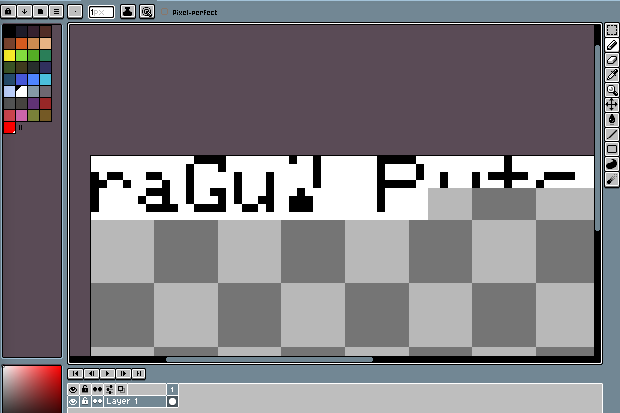
- I wrote the following python script to render the graphics in ASCII:
import binascii with open("pixel_data.txt", "r") as f: input_ = f.read().split(" ") bin_input = [] new_row = [] for ele in input_: new_row.append(f'{int(ele,16):0>8b}') if len(new_row) == 128: bin_input.append(new_row) new_row = [] for row in range(len(bin_input)): for i in range(8): for col in range(len(bin_input[row])): if bin_input[row][col][-i-1] == "1": print("#", end=" ") else: print("_", end=" ") print("")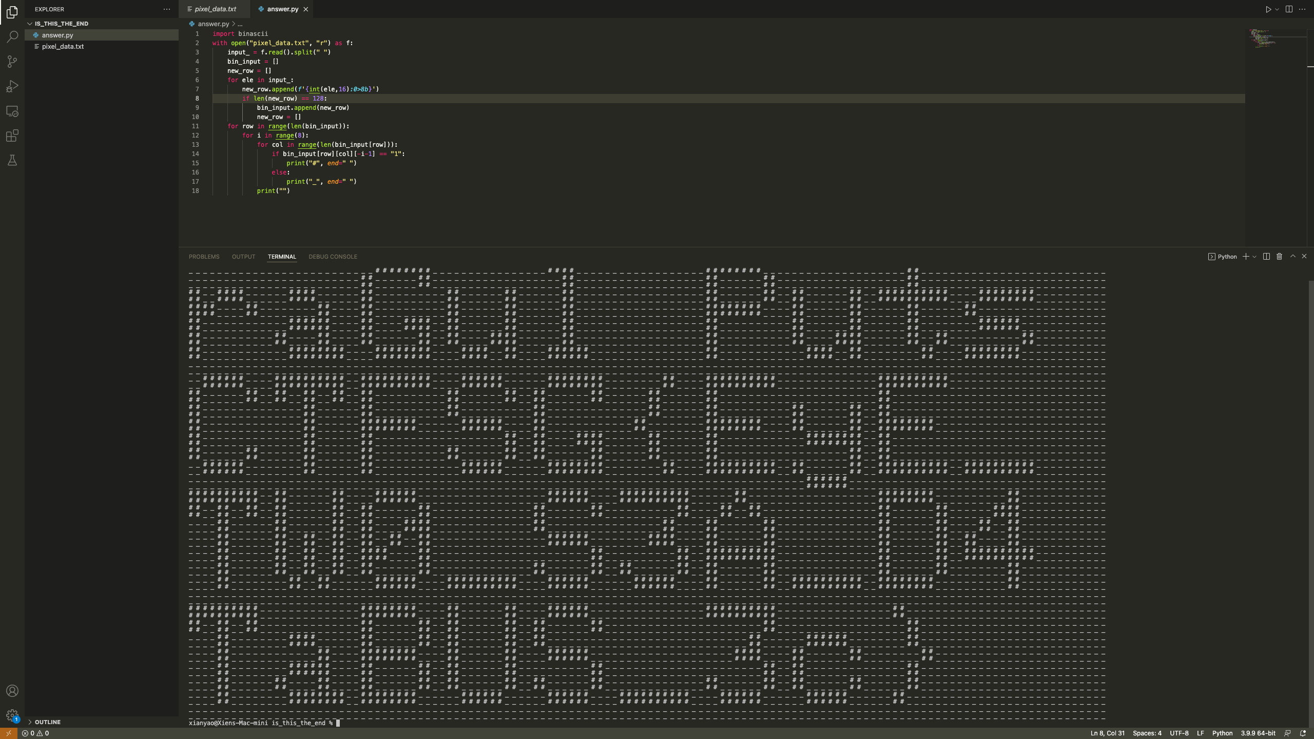 CTFSG{EyE_TWO_S3A_D4TaBUS_3c}
- I tried to draw out the graphics manually in aesprite, and although there were a lot of inconsistensies due to human error, letter forms were clearly visible.
A short interview with @R4GUL#8503, the author of the challenge SIGINT
Tell me a bit about yourself.
I play CTFs and I am a part of CTFSG.
What got you into hardware?
I actually started off doing robotics before I started doing cyber.
What is the most interesting hardware-related thing you’ve done?
Why and how did you make this challenge?
There aren’t many hardware challenges in CTFs, so I decided to do it for greater diversity. How did I do it? I built a setup, got a signal analyser, and just got a voltage signal.
Any last words?
Not much. I hope more people are interested in hardware.